A more refined version of the modular DIY CNC anyone can have in their home office or workshop. This version features better rails and a more practical work space ratio but still has the potential to upgrade later if needed. Visit our shop to purchase some of the plates directly to be 3D printed or modified!
This project was originally posted on Instructables
Overview
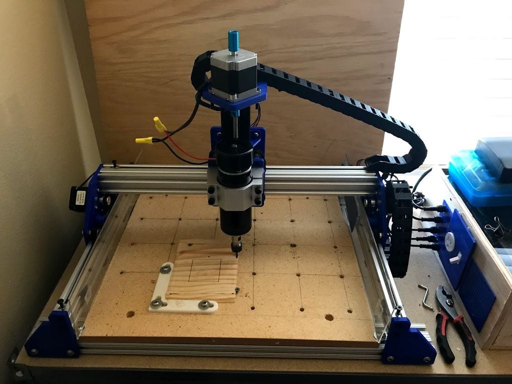
I built my first CNC about a year ago and learned a lot from the process. As an engineer I’m always looking at ways to improve things, and my first machine was no exception. The process began with some small changes which quickly turned into the opportunity to overhaul the design even more to better suit my needs (an overview of these changes is detailed in the next step).
For the previous iteration and documentation of my design, refer to my original Instructable: Modular DIY CNC Machine which has all the files included for easy access. For this Instructable, however, I’ve decided to include technical drawings of the plates rather than actual part files. The parts themselves are fairly easy to create so this shouldn’t be a large inconvenience for most, especially if you plan on actually using a CNC since CAD is a big step in the whole CNC proces. In the future I’ll provide the actual part files for a fee and may consider offering actual printed parts for purchase also for those without a 3D printer.
Whether you’ve already made a CNC or this is your first one, I hope you find this Instructable helpful. Feel free to leave any comments or questions down below and if you like what you see please vote for me in the Build a Tool Contest!
Step 1: The Design
After building my first CNC I realized there were a few things I incorporated that I didn’t fully need in the design. Namely:
1. The size. I originally wanted a CNC that was a decent size and could handle larger jobs, however I found myself only using the front half or so of the machine. This machine has a smaller cut area and I also changed the width and length proportions so wider pieces could be fit on the spoilboard. I did, however, leave the front and back of the machine open to allow for longer pieces to still fit by utilizing a pass through or indexing-like system (similar to one of the Glowforge models).
2. Rigidity. The original machine had some play in the Z-axis when I mounted a router or spindle and when certain cuts were performed. For this design I chose to incorporate eccentric spacers on all the axis to take away this play and give a tighter grip to the framing.
3. Materials. The previous machine was made out of 80/20 t-slot framing mainly because 80/20.net would cut the pieces to length and I wouldn’t need to use any specialty tools (I essentially had no tools at the time). Through various other projects I’ve been able to grow my tool collection, and chose to order v-slot extrusions from Openbuilds and cut it to length myself. Additionally, I have a larger 3D printer now so I was able to print all the plates myself and didn’t have to get them laser cut elsewhere. Initially I planned to use the 3D plates as prototypes before I ordered laser cut pieces or aluminum plates, however they seem to be holding up so the other options aren’t needed.
4. Electronics. One of my least favorite parts of the previous machine was the electronics bundling. This made it hard to move the machine around, and overall looked fairly messy. For this machine I chose to have a separate box with all the electrical components inside and adapters that can easily be detached if I need to move the machine. The box also has other features included in it that make it easier to use the machine and safer to operate. I also chose to omit limit switches for this design since I didn’t use them much, but these can be added back in easily if needed later on.
————————————————–
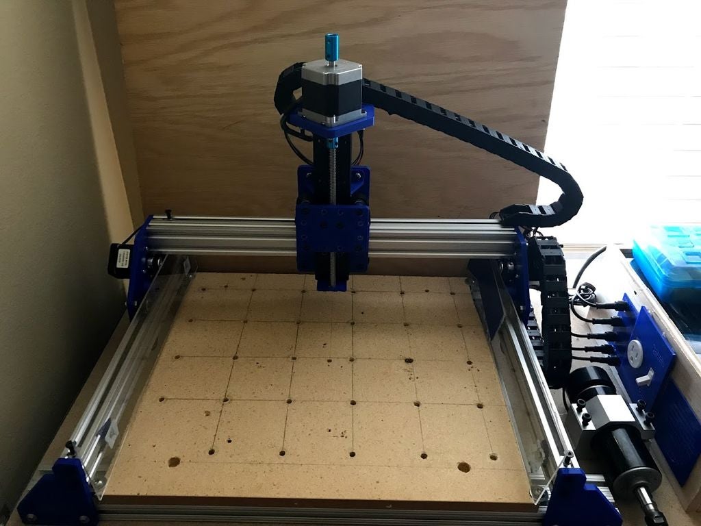
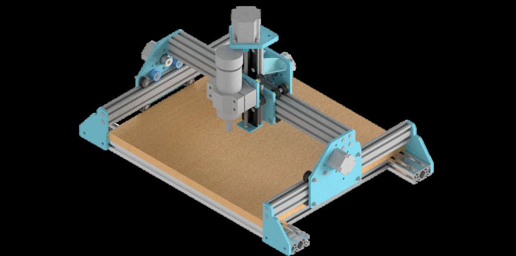
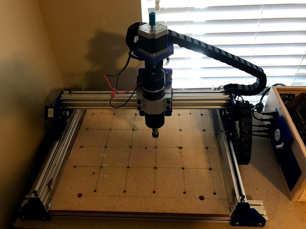
The area of travel for the cutting tool (500W spindle) is about 13″ in the X, 9.5″ in the Y and 5″ in the Z, but this could be increased if longer aluminum extrusions were used. The gantry moves along the Y-axis via belt drive with motors on either side of the frame while the X-axis moves perpendicular to the Y-axis along the gantry, also via belt drive. Attached to the X-axis is the Z-axis, which moves up and down via screw drive. I’ve also incorporated mounting holes on the plates to allow the axes to be converted to screw drive, however this still needs work to mount the motors and make sure everything else lines up.
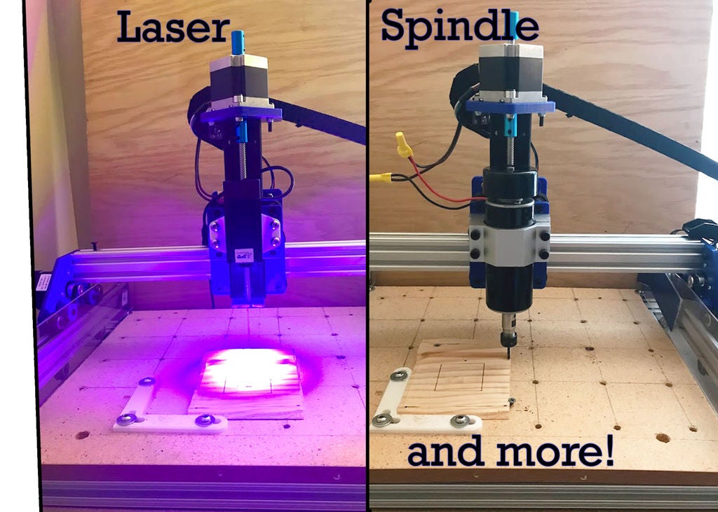
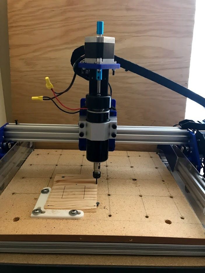
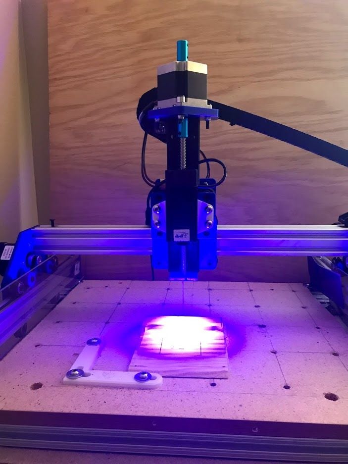
The Z-axis still has a basic attachment scheme, meaning multiple tools can be attached so long as an adapter is designed with matching mounting holes. For my purpose, my 500W air powered spindle can attach and I’ve created an attachment for my 2.5W laser. You could also design an adapter for a pen or even a 3D printer head to name a few options.
The overall cost of this machine ends up being around $325, not including the spindle or laser. I hope you find this Instructable useful if you decide to build your own CNC. There are a lot of resources out there for doing so, and I hope I’ve created something that helps centralize a small portion of this information.
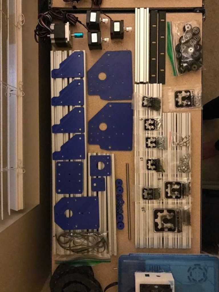
Step 2: Bill of Materials
Frame:
The v-slot aluminum extrusions all come from Openbuilds.com but there are other suppliers out there that might be cheaper. The pieces came oversized but can easily be cut with a circular saw. The nature of the design itself allows for various frame configurations so you can adjust the extrusion proportions to fit your specific needs.
Carriages and Drivetrain:
The X and Y axes move using carriages which reduce friction and make it easy for attaching the extrusions, motors, and other electronics. For the carriage plates, I initially was going to use 1/8″ aluminum plates but wanted to make sure I had a plate design that worked first. I started with 1/8″ 3D printed PLA plates and was happy with the fit so ditched the metal plate idea for the time being. Currently I’m using 1/4″ thick PLA plates which add more rigidity than the 1/8″ ones. The carriages also use V-slot wheels with bearings, which start to get costly as you add them up. However, I’ve found the wheels to work very well, and they increase the overall machine effectiveness. The motors on each carriage then use a belt drive system to move along the frame.
For the Z-axis, I added some V rails to the extrusions so the wheels weren’t cantilevered as far from the mounting plate. This axis is also driven using a screw and delrin nut directly attached to a NEMA 23 motor which add some rigidity and more power.
Electronics:
I already had a lot of the electronics from my previous build so I stuck with what I had to save some money. The CNC is still powered by an Arduino Uno with CNC shield and stepper drivers. Two NEMA 17 motors power the Y axis while one NEMA 17 motor powers the X axis. The Z axis is powered by a NEMA 23 motor. More information on the electronics box can be found in Step 8.
Custom Parts:
Drawings for all the plates are attached to this Instructable so you can CAD them yourself. They’re pretty simple and can be easily recreated no matter your CAD level. The parts can then be 3D printed, machined out of aluminum, laser cut, etc… Additionally I’ve tried to design the plates so they can accept either NEMA 17 or NEMA 23 motors, however I have not tested out most of the NEMA 23 motor holes to see if there are any issues. Some plates also have spots for delrin nut blocks to be mounted on if you’d rather use a threaded rod instead of a belt driven system. Again, this has not been fully tested so there may be issues. You’ll also need to design a mount to hold the motors if you want to go the threaded rod route.
Note that all important dimensions should be included in the drawings, however I did not spend the time to clean up the drawings and bring them up to ANSI standards. There should be enough information included to generate the plates regardless though but let me know if any critical dimensions are missing.
————————————————–
Materials List:
– Estimated Cost: ~$325 (not including spindle or laser)
– See attached Excel file for all parts, prices, and links. All plate files are included in drawing format while more complex parts have the .STP file included. Standard disclaimer: Some parts might be missing from assembly materials lists and images. I’ve attempted to include everything necessary but I might have missed some parts.
– Note: A lot of the screws listed are meant to work for 1/8″ thick plates. If you’re using 1/4″ thick plates you might need to add counterbores or use longer hardware so everything fits correctly. Additionally, all assembly photos show 1/8″ plates instead of the 1/4″ ones I currently have but the assembly is the same regardless.
Step 3: Tools Needed and Parts Prep
Tools Needed
The tools used are as follows:
1. Drill
2. Allen wrench set / precision screwdriver set
3. 3D Printer (can also have pieces printed via 3D Printing services or make them out of metal)
4. Hot glue gun
5. Tap and die set (optional)
6. Multimeter (optional, but helpful)
7. Circular saw
Parts Prep
A few parts will need to be prepared in order to fully fit for the machine.
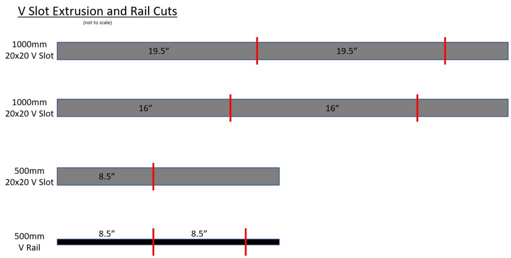
– The V-slot extrusion and V-slot rails need to be cut to length with a circular saw (see attached image or use dimensions for each piece in BOM)
– Use the self tapping screws to tap the ends of the V-slot rails so assembly is easier later. This takes some time and might be easier with a separate tap set.
– Some 3D printed parts may need to have the holes enlarged/test fit to make for easy assembly later on.
– The M8 rod needs to be cut to length
Step 4: Y Carriage
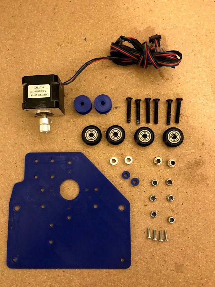
Materials:
Multiply all quantities by 2 so you can create both Y Carriages.

Note: The hardware included is for a 1/8″ plate. If using a 1/4″ plate then increase the hardware size by 5mm to 10mm or add counterbores to the plates.
Steps:
1) Assemble (1) M5 x 30mm Bolt through (1) Delrin Wheel and (1) Eccentric Nut as shown. Create (2) of these assemblies.

2) Put each assembly through each of the Eccentric Spacer holes in the Y Axis Plate. Make sure the Eccentric Spacer is fully seated in the plate. Tighten the other side of each bolt with a M5 Lock Nut.


3) Take the other (2) M5 x 30mm Bolts and assemble through (1) Delrin Wheel and (1) Aluminum Spacer 6mm each as shown.

4) Put each assembly through each of the two holes below the Eccentric Spacer holes in the Y Axis Plate. Tighten the other side of each bolt with a M5 Lock Nut.

5) Check the fit of the wheels on a Makerslide piece. The carriage should move smoothly back and forth and adjust the Eccentric Spacer to adjust the grip (this can be fine tuned later).

6) Take the last (2) M5 x 30mm Bolts and assemble each through (1) Smooth Idler and (1) Idler Spacer. Put these through the Idler holes on the Y Axis Plate and tighten with M5 Lock Nuts.

7) Attach a Belt Pulley to the NEMA 17 shaft. Attach this assembly to the Y Axis Plate using (4) M3 x 10mm Screws.

8) Repeat Steps 1 through 7 so you have a mirror image of this assembly as shown.

Step 5: Z Axis Assembly and X Carriage
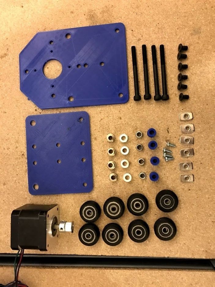
Materials:
The Z Axis Assembly will be assembled first and then attached to the X Carriage once it’s assembled.


Note:The hardware included is for a 1/8″ plate. If using a 1/4″ plate then increase the hardware size by 5mm to 10mm or add counterbores to the plates.
Steps:
1) Assemble (1) M5 x 30mm Screw through one of the Z Axis Mounting Plate Eccentric Spacer hole. On the other end assemble on (1) Eccentric Spacer, (1) Spacer 5.635mm, (1) Delrin Wheel and (1) M5 Lock Nut. Repeat this for the second Eccentric Spacer hole on the Z Axis Mounting Plate.


2) Assembly (1) M5 x 30mm Screw through one of the Z Axis Mounting Plate holes opposite an Eccentric Spacer hole. On the other end assemble on (1) Spacer 11.635mm, (1) Delrin Wheel and (1) M5 Lock Nut. Repeat this for the second hole on the Z Axis Mounting Plate opposite an Eccentric Spacer hole.


3) Assemble the Delrin Nut Block onto the 8mm Rod. (Note an anti-backlash nut is shown. I found this one to be too tight on the thread so I swapped it out for the Delrin Nut block).

Attach the Delrin Nut Block to the Z Axis Mounting Plate using (2) M5 x 15mm Screws and (2) M5 Lock Nuts.


4) Take the V Slot 20 x 40 x 8.5″ and attach the Z Axis Top Plate using (2) Self Tapping Screws. Note that the plate shown is a previous iteration. The actual plate is thicker and has other features so the motor doesn’t interfere with hardware.


5) Take (1) Open Rail V Rail 8.5″ and attach (4) M5 x 8mm Screws through the mounting holes and thread (4) M5 Tee Nuts onto the other ends. Note the image shows this assembled backwards. The recessed side should have the Tee Nuts against it.

Repeat this with the other Open Rail V Rail 8.5″, (4) M5 x 8mm Screws and (4) M5 Tee Nuts. Again these assemblies are backwards in the pictures. If assembled this way then the spacing between the Z Mounting Plate and the V Rails will be off.


6) Slide the (2) V Rail assemblies onto the V Slot assembly. Make sure the bottom of the V Rails are flush with the bottom of the V Slot. Tighten the M5 Screws while making sure the lip of the V Rails are pushed flush with the V Slot. Again the V Rails are backwards in the picture. The lips on the far right and left should be flipped over to the other side (see the image in Step 15 below)..

7) Attach (1) NEMA 23 Coupler to the NEMA 23 motor. Attach this to the Z Axis Top Plate using (4) M5 x 30mm screws and (3) M5 Lock Nuts. There isn’t enough clearance for the last M5 Lock Nut to be placed on the back corner of the motor so I just used the M5 screw to index the hole. Finally, slide the Mounting Plate assembly on the V Rails and into the NEMA 23 Coupler and tighten the coupler set screw.


The Z Axis assembly is now complete and will be attached to the X Axis Carriage next.
8) Attach (2) Eccentric Spacers to the X Axis Plate Front and (2) Eccentric Spacers to the X Axis Plate Back using the Eccentric Spacer holes.

9) Take the X Axis Plate Front and on the opposite side of the Eccentric Spacers attach (6) M5 x 8mm Screws through the (6) middle holes and secure with (6) M5 Tee Nuts.

10) Slide this assembly onto the back of the Z Axis assembly and make sure the bottom edges are flush. Tighten the M5 Screws to secure the plate in place.

11) Attach the NEMA 17 motor to the X Axis Plate Back using (4) M3 x 10mm screws. Also attach the Belt Pulley onto the shaft of the NEMA 17.

12) Assembly (1) M5 x 55mm screw through the X Axis Plate Front top hole, through the Eccentric Spacer then (1) Delrin Wheel, (1) Spacer 9.77mm, (1) Delrin Wheel and lastly the Eccentric Spacer and X Axis Plate Back top hole. Use (1) M5 Lock Nut to hold everything in place. Repeat this for the other top hole of the plates and make sure all Eccentric Spacers are seated in the plate holes.

13) Assemble (1) M5 x 55mm screw through the X Axis Plate Front bottom hole, through (1) Aluminum Spacer 6mm then (1) Delrin Wheel, (1) Spacer 9.77mm, (1) Delrin Wheel and lastly (1) Aluminum Spacer 6mm and the X Axis Plate Back bottom hole. Use (1) M5 Lock Nut to hold everything in place and repeat this for the other bottom hole of the plates.

14) Check to make sure the X/Z Axis Assembly has the correct spacing by sliding (2) 20 x 40 V Slots between the Delrin Wheels. Adjust the Eccentric Spacers to so the carriage moves smoothly back and forth.

15) Attach the Z Axis Bottom Plate to the bottom of the X/Z Axis Assembly using (2) Self Tapping Screws.

Note the Threaded Rod still needs to be cut and should be flush with the Z Axis Bottom Plate. The V Rails are also still shown to be backwards. The correct orientation is like so:


The X/Z Axis Assembly is now complete.
Note in my assembly I also added in a support bracket between the X Axis Plate Front to stiffen up the assemblies.

Step 6: Gantry Assembly
Materials:

Steps:
1) Take (1) Y Carriage and make sure it’s well supported. Attach it to the (2) V Slot 20 x 40 x 19.5″ extrusions using (4) Self Tapping Screws.


2) Slide an extra M5 screw and M5 Tee Nut into the extrusion then slide on the X/Z Assembly onto the extrusions. Slide a second M5 screw and M5 Tee Nut into the same extrusion. These screws will be used to hold the belt in place.


3) Attach the second Y Carriage onto the Gantry Assembly using (4) Self Tapping Screws. The assembly is now complete.

Step 7: Final Assembly
Materials:

Not listed:Belts, extra M5 screw and tee nut, 1010 x 12″ extrusions and additional 1/4″ cap screws, 1/4″ tee nuts and brackets.
Steps:
1) Attach (1) Leg Brace onto (1) V Slot 20 x 40 x 16″ extrusion using (2) Self Tapping Screws. Assemble (2) 1/4″ Cap Screws through the bottom holes of the Leg Brace and attach (2) 1/4″ Tee Nuts on the other ends. Slide an extra M5 screw and M5 Tee Nut into the extrusion. Repeat so you have two of these assemblies.


2) Slide the assemblies from the previous step onto (1) 1020 x 24″ extrusion so the flat edge is towards the inside of the extrusion. Don’t tighten the 1/4″ Cap Screws yet. Note you don’t have to use the 1020 extrusion but can instead use another piece of V Slot extrusion and the appropriate hardware. I used this extrusion because I already had it lying around.


3) Turn the assembly 180 degrees and slide the Gantry Assembly onto the (2) V Slot extrusions. Slide an extra M5 screw and M5 Tee Nut into each of the extrusion.


4) Attach (2) Leg Braces to the (2) V Slot extrusions using (4) Self Tapping Screws.

Use (4) 1/4″ Cap Screws and (4) 1/4″ Tee Nuts to the 1020 x 24″ extrusion.

5) Use a square to make sure everything is square before tightening the cap screws.


6) Attach some spare 8020 brackets to a 12″ 1010 extrusion using some washers, cap screw and tee nuts. Slide these extrusions between the 1020 extrusions and tighten when square. I used (3) of these assemblies (one below each leg extrusion and one in the middle of the machine).


Make sure everything is square and then tighten all the cap screws.

Once everything is tightened then testing moving the axes around without the belts to make sure everything runs smoothly. Tighten or loosen the Eccentric Spacers as necessary.
7) Thread (1) Belt under (1) of the M5 screws and tighten the screw to hold the end in place. Feed the belt under the Smooth Idler, over the Belt Pulley and under the other Smooth Idler.

Slide the other end under the other M5 screw and pull the belt tight to apply tension. Tighten the screw to hold the belt in place. Repeat this step for the other Y Axis motor and X Axis motor.

8) The mechanical components of the machine are complete. I also slid some cap screws into the 8020 extrusions to help fix the wasteboard (shown in the second image). Also shown is a plexiglass shield I have on either extrusion attached by magnets.


Step 8: Electronics Routing
I recommend testing all electronics first before placing them. This makes it easier to troubleshoot everything, however this can still be done if the parts have been placed.
Test the Electronics
The general electronics are a duplicate from my previous machine. Like before, make sure to hook up the power supply correctly, otherwise you may short out the components and could destroy your electronics. For an extra precaution, I initially plugged the power supply into a surge protector.
To hook up the supply, I took an old computer power adapter and stripped down the cord so the live, negative and ground wires are showing. Make sure whatever cable you use has a ground connection. You can use a multi-meter to determine which wire is which, or you can consult online sources since most cables are the same. Once I determined which wire is which I labeled them so I didn’t get them mixed up later on. I then hooked them up and plugged the power supply into the outlet and measured the output voltage using a multi-meter to ensure I was getting the 24V I needed. My power supply had a potentiometer on it so I tuned the supply to get the value I wanted.
Prepare the Arduino
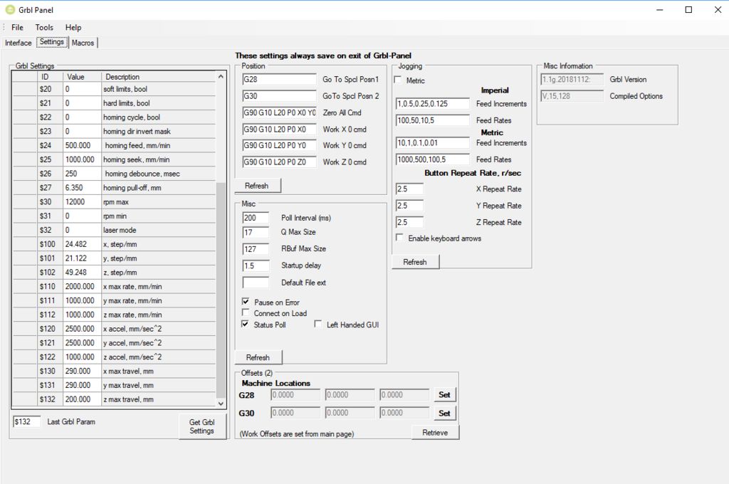
The next step is to load GRBL onto the Arduino Uno as this is what communicates with the motors and transmits the G-Code to the CNC. I placed the motor shield on top of the Arduino Uno and the motor drivers on top of that. It’s best to test one motor and motor driver at a time to ensure GRBL is running correctly. Once you’ve determined GRBL works, you can hook up the rest of the motors and play with them. I thought this step was pretty cool as it’s one of the main things that makes a CNC a CNC. There are various programs online to actually send GCode to the Arduino and most of them are pretty light and self explanatory. I like Grbl-Panel the best (linked below), but there are several other programs available that you can find with a quick search. I also attached a few guides I used for installing GRBL and other electronic troubleshooting:
At this point you can also use the jumpers included with the CNC kit for configuring the 4th axis and microstepping. Configuring the 4th axis will tell the shield which axis the motor plugged into the “A” port on the board controls. For this CNC, place two jumpers across the Y pins (detailed here under 4th Axis Configuration) since the two motors control the Y axis. Microstepping is discussed further in the next step.
CAUTION: Make sure the power supply is off when messing with the Arduino and CNC Shield. If you don’t then you run the risk of damaging the motor drivers, the shield or even the Arduino. Trust me, I learned this the hard way and it’s not fun trying to figure out what’s causing the problem.
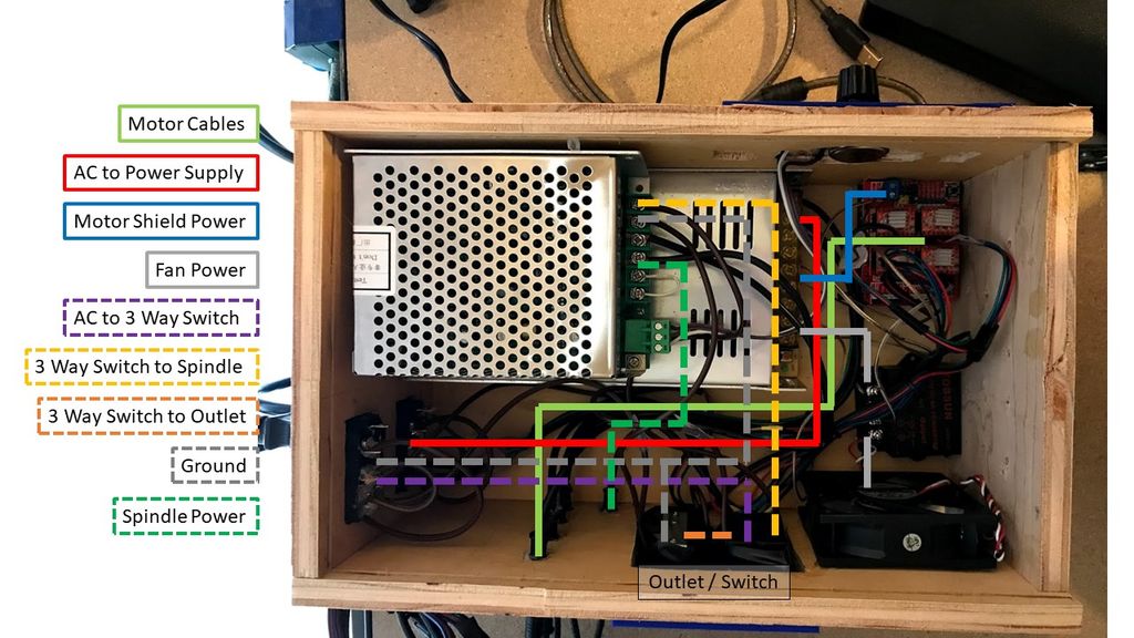
Finalized Routing
Once I had all the electronics working again I routed the cables to the back right of the machine through various drag chains.


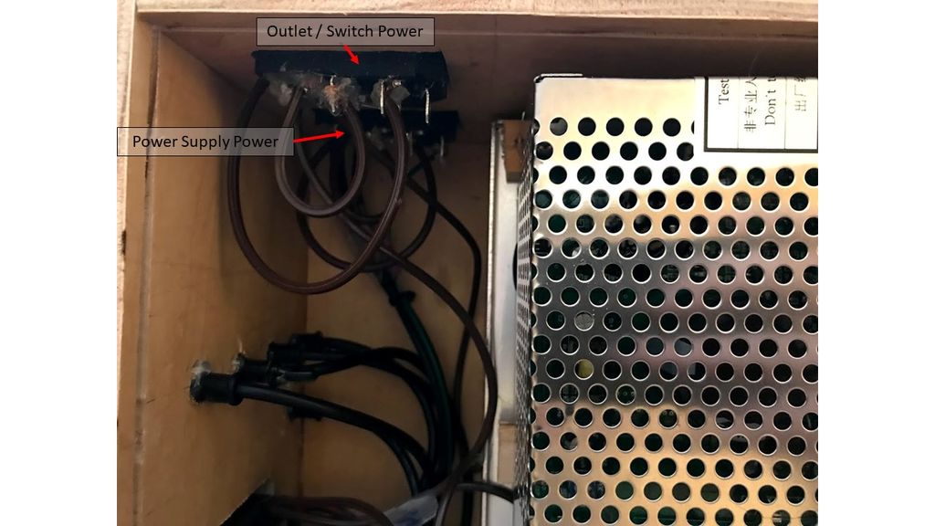
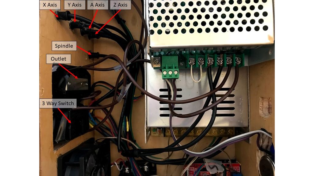
I then laid out the power supplies and other electronics I wanted to hide in the box so I knew what size I should cut my scrap wood into. My box ended up being 8.5″W x 5.5″H x 13″D and has an acrylic window on the top for easy access. I also incorporated holes in one side of the box for the fan, all four motor connections and a spindle connection. Also on this side of the box I added in a 3 way switch that splits a secondary AC current so I can choose if I want to power an outlet or the spindle. I also plan on adding in a relay to the circuit to allow the Arduino to turn on or off the tool whenever the job starts or stops.

On the opposite side of the box there are cutouts for the Arduino connections and a spot for the spindle speed control.

Finally, the back of the box has the power adapter components so I can easily unplug power for the machine itself or the spindle / outlet current.

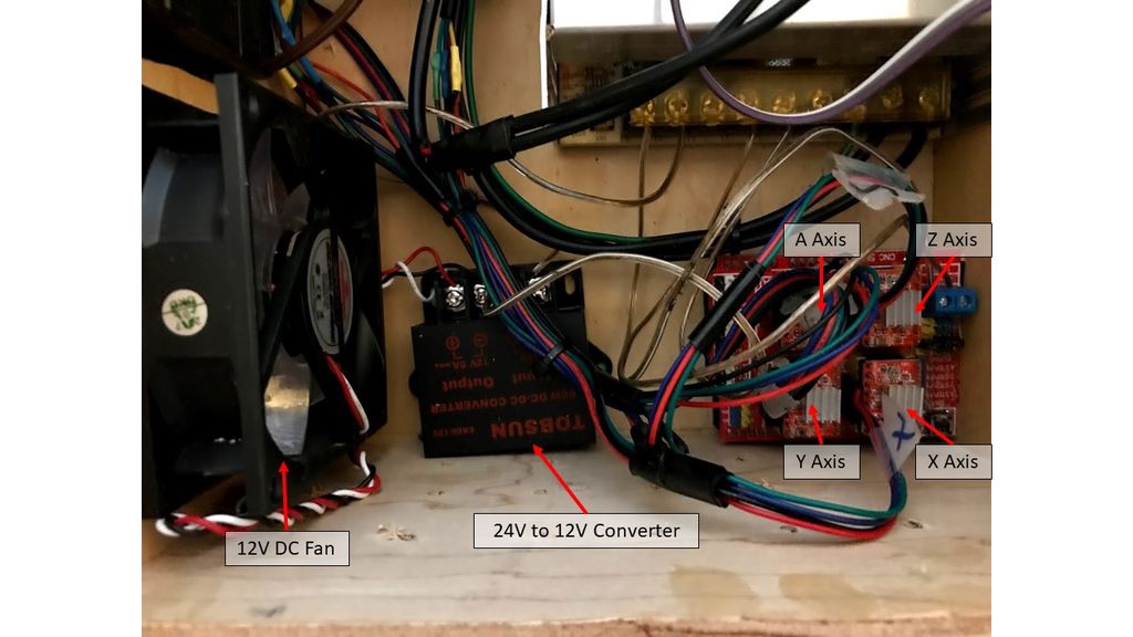
In the initial design I had powered the fan with the Arduino itself but this meant it was only getting around 5V (less than half of what it’s rated for). I added in a 24V to 12V converter so I could power the fan straight from the power supply at its full power making it easy to cool down all the components.
Step 9: Configure the Electronics
Once everything’s been put together your almost done to run your first test program. However, the CNC won’t fully have the right settings, meaning your program won’t be accurately executed. The CNC must now be calibrated so it actually goes where the Gcode tells it to. For instance, the CNC doesn’t know how far one revolution of the motor actually makes the machine move. To configure this, you need to set the step/mm which tell the motors how far they need to rotate to move the amount specified in the Gcode.
You may need to iterate through the step values until you have a value that produces the most accurate results. The main formula you need is:
- (New Step Value A) = (Old Step Value) * (Traveled Distance) / (Measured Distance)
The best way to find the step value is:
- Set the step value in GRBL
- Mark the machine starting location on each axis using tape or a marker
- Use the software to move the machine a specified amount
- Compare the actual amount moved with the desired amount and use the above formula to calculate the new step value. For example, you may tell the machine to move 1″ but it really measures out to be 0.75″ so use the formula to find the new step value.
- Repeat until you have an actual movement value that matches the desired value (i.e. you tell the machine to move 1″ and it actually moves 1″ in that direction)
You can also use microstepping which makes the movement smoother at a loss of torque. For this reason, it’s best to minimize the overall machine friction in order to have the smoothest movement possible. To incorporate this, you need to connect the appropriate jumpers on the CNC shield and adjust the step value. The new formula you’ll need is:
- (New Step Value B) = (New Step Value A) / (Microstepping Fraction) where New Step Value A is still calculated using the formula above.
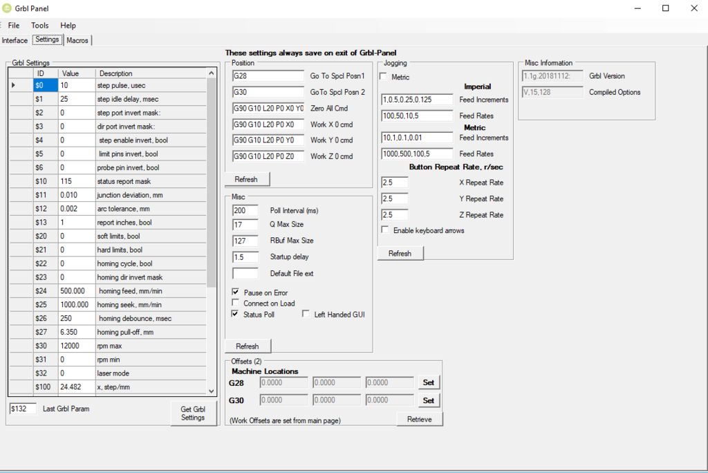
For my machine I used the following settings:
- X-Axis: 24.482 step/mm (Microstep = 1/4)
- Y-Axis: 21.122 step/mm (Microstep = 1/4)
- Z-Axis: 49.248 step/mm (Microstep = 1/2)
I also used the following links for reference:
GBRLInterfacing Programs
The following programs can be used to set GRBL settings and send the G-Code:
If Your Stepper Motors Aren’t Moving
If your motors are plugged in but they don’t move when you send the commands, make sure the correct current or voltage is being sent to the stepper drivers. You can measure this with a multimeter as mentioned here, then adjust the potentiometer until the correct value is achieved. Your should run the motors per the specifications. If you go over these values you run the risk of damaging the motors or stepper drivers. Also make sure all your electrical connections are sufficient. This can be tedious but sometimes inspecting one component at a time is the best way to find the culprit for your problems.
Step 10: Run the Machine!
Now comes the fun part: MAKE STUFF! For this you just need to create a design, make the Gcode, and send this to the machine. There are many different ways to create the code, but I’ve found success using Easel which is meant for the XCarve, however you can just change the settings to match your machine and export the Gcode. The basic steps for running the machine after generating Gcode is as follows:
- Secure your work piece to the wasteboard.
- Move the machine to the furthest point of your work piece relative to the homed location (machine zero). Lower the Z-Axis so it just touches the work piece.
- Zero the machine. Your work coordinates should now be zero (work zero).
- Run the Gcode.
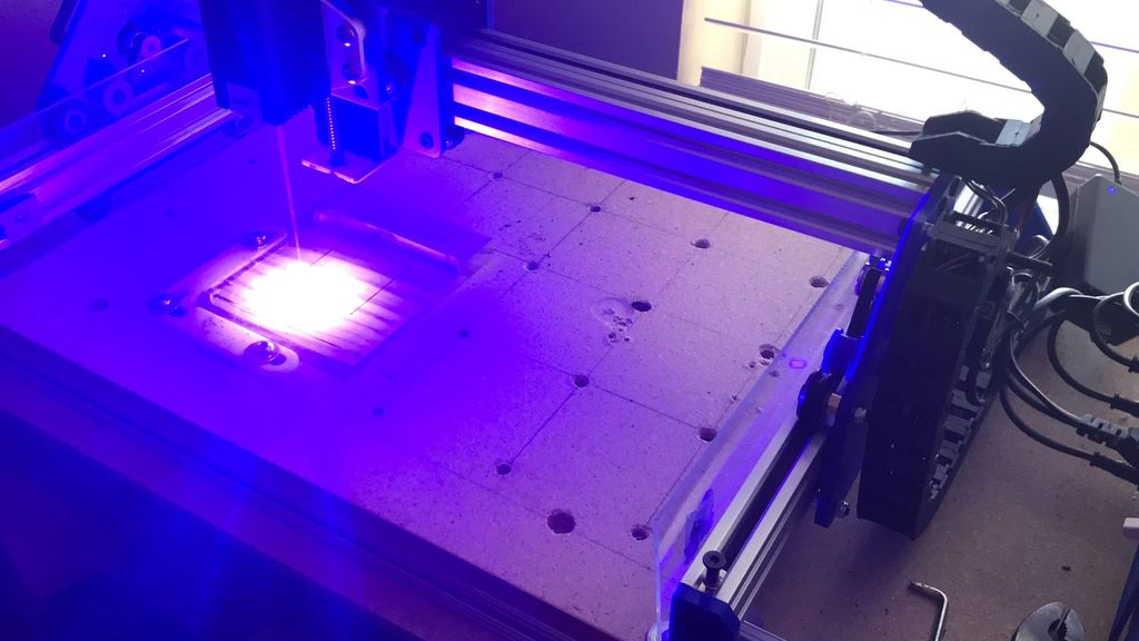
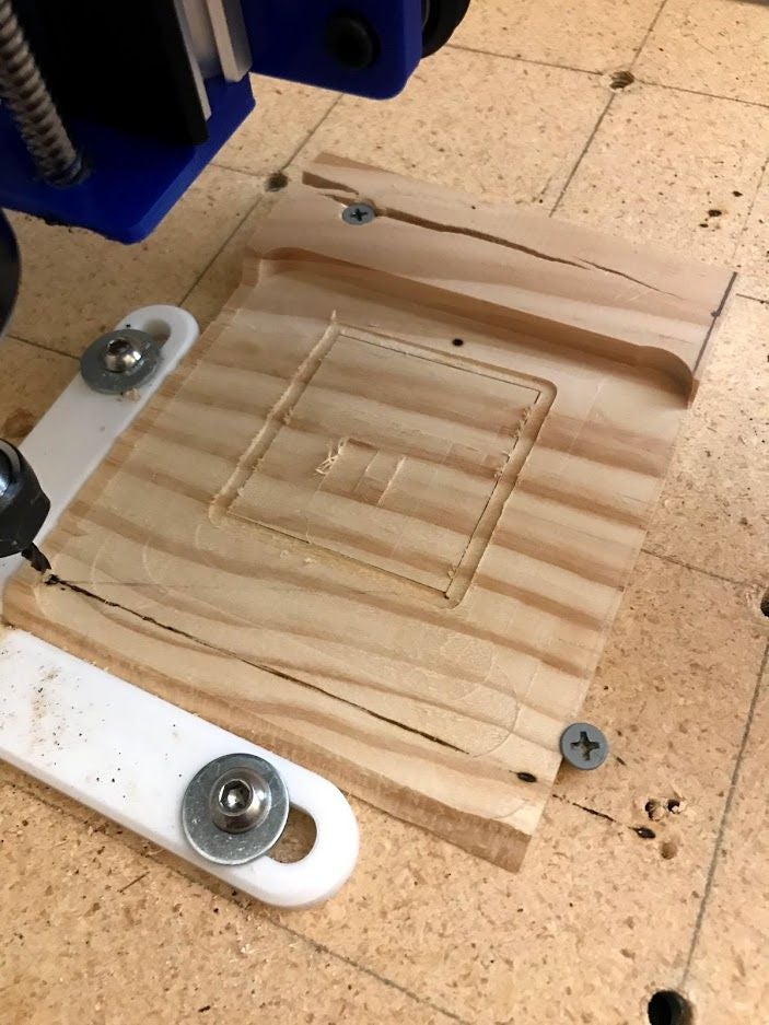
Easel runs you through these steps so it should be pretty straight forward. I also run the Gcode before having any tools in to avoid damaging the tool if the Gcode isn’t quite right, or I just use a scrap piece of material rather than wasting the actual work piece. I quickly tested the machine by laser engraving a square and then doing a test cut using the spindle. Some of the feed settings and depth cuts still need to be optimized but other than that the square came out well.
————————————————–
Clamps:
There are many different types of clamps out there so it mainly depends on user preference. I like the ones made by Marius Hornberger or you can find ones on Thingiverse too. Alternatively you can also use tape but make sure the workpiece is securely fastened to the wasteboard so it doesn’t fly off.
Tips and Tricks:
- If the motors are skipping steps try adjusting the voltages. The motors may not be getting enough voltage/current.
- Regularly check the belts to make sure they’re still tensioned
- If you use a relay then put M3 at the beginning of your Gcode and M5 at the end to turn the power to the outlet ON or OFF respectively. This is especially useful if you’re using a laser so the laser doesn’t drag across the workpiece and cause unwanted burn marks.
- If your machine isn’t moving very quickly or movement seems clunky, try adjusting GRBL settings. I found success in changing the acceleration and speed until I got movement I was happy with.
Possible Improvements:
- Use NEMA 23 motors on all axes for more power
- Switch from belt drive to threaded rods for more reliability and precision
- Use a knob instead of a coupler on top of the Z-axis to make it more ergonomical
————————————————–
That’s it you’re all done creating and setting up your own CNC! Hopefully this Instructable provides yet another inspiration for how to make your own machine and how certain designs are more efficient than others. Thanks for reading through this Instructable, and feel free to leave comments and questions below!
Step 11: Next Steps
As always there are improvements to be made. As of right now I can think of the following:
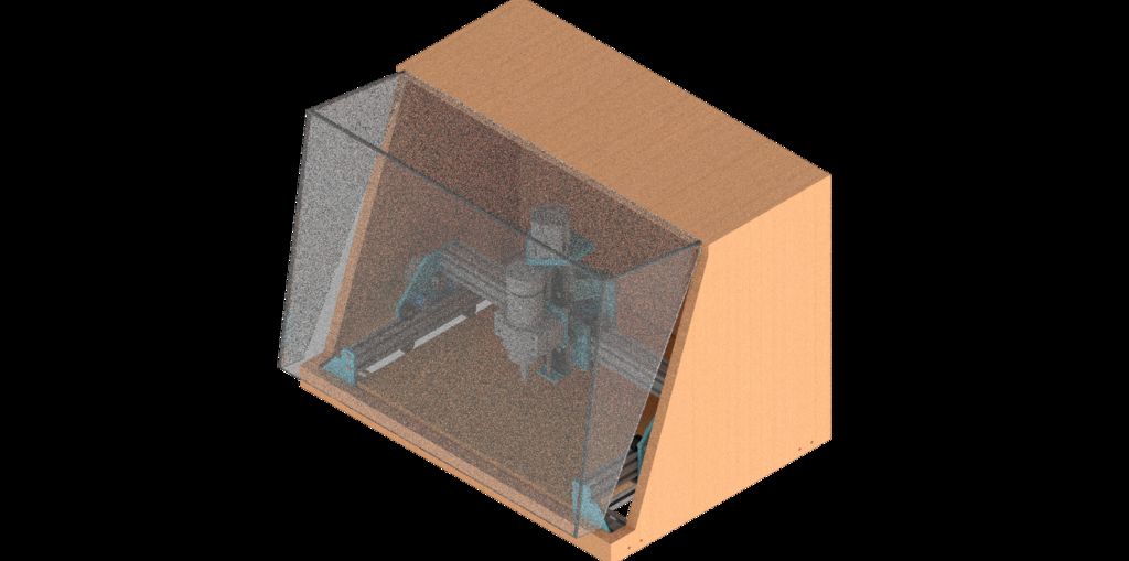
– Add an enclosure to reduce noise and contain dust
– Dust shoe to help contain dust
– Raspberry Pi to run the CNC without needing to always plug in my laptop
– Swap the 3D printed plates out for metal ones or machined plastic
– Suggestions?
Hello,
Your CNC project looks great to me! I need to build one myself but a larger one which is able to cut 2440 x 1220 mm plywood sheets in order to build my own house using the Wiki House concept (wikihouse.cc). so the CNC machine size should be adapted. Besides the length of the aluminium profiles, are there other components (motors, 3D printed parts,…) I should adapt?
Many thanks in advance for your feedback.
Marc Devriendt
Hi Marc,
Thanks for the kind words. For larger plywood sheets you’ll want larger aluminum profiles and larger motors to handle the increase in size and maintain machine rigidity. It’s likely you can use a similar design, but will need to do some redesign to make sure it can handle the larger cut capacity without sacrificing quality.
Hope this helps!