This instruction is specifically for making a blade for a Ben Solo Legacy Lightsaber purchased from Disneyland’s Galaxy’s Edge in Anaheim, CA, however similar steps can be taken for making your own blade for a different lightsaber. Follow along for inspiration for making your own customizable blade!
Disclaimer: There will be permanent changes made to the lightsaber hilt. This hilt is not cheap so be warned ahead of time and do not proceed if you’re not okay with this.
Background
If you don’t know, Disneyland’s Galaxy’s Edge is a great place for any Star Wars fan. One of the experiences they offer is the ability to build your own custom lightsaber at Savi’s Workshop, however this is in high demand and requires reservations in advance. Another option they have is the ability to purchase a character based “legacy” lightsaber hilt in one of the shops, however these hilts don’t include the blade and the blades for purchase can only be one color.
My initial plan was to purchase the custom lightsaber from Savi’s and then use an RFID writer to change the blade color to whatever I wanted. Unfortunately the day we went to the park there were no reservations left to build your own lightsaber, so I chose to purchase a pre-made one instead. I chose to not purchase the blade with the hilt so I could make my own and program it to be whatever color I’d like.


This project was inspired by Bob from I Like to Make Stuff, who made his own custom lightsaber so check it out!
Note: If you’re concerned with cost, it’s cheaper to purchase the legacy hilt and legacy blade from Galaxy’s Edge (however some blades do cost more depending on which hilt you go with). If you choose this route, the resultant lightsaber will be only one color. The cost of this project is comparable to purchasing a Savi’s workshop custom lightaber and then an RFID writer to make the blade whatever color you want.
Step 1: Project Features
Again, there are some permanent modifications that need to be made to the hilt in order to support the new electronics. If you are uncomfortable with this then do not proceed. The intent here is that you can still purchase the “legacy” blade and it should still work with the hilt, however this was not tested and can’t be confirmed. The changes made were also only performed on a Ben Solo legacy blade, so if you have a different blade then certain details will likely be different. Any changes you do to your hilt by following these instructions is at your own risk. We are not liable for any damage that occurs.
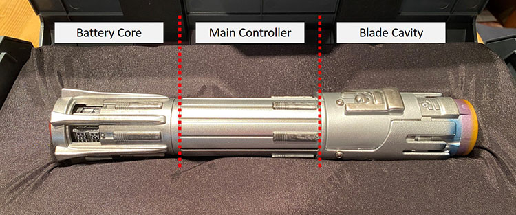
The components of the hilt includes the battery core (contains the batteries and a speaker), main controller segment (contents unknown) and blade cavity (with on and off switch). The main controller segment is sealed and can’t be accessed (at least without destroying the hilt completely). The goal here was to use the existing battery core and then add in my own microcontroller which would control an LED strip and output sounds to the speaker. The microcontroller used is a Teensy 3.2 with a Prop Shield to allow control of the LED strips and speaker. The actual blade assembly is removable and holds the Teensy, Prop Shield, and LED strips which are in a polycarbonate tube. The blade assembly slides into the hilt and be held in place with a custom 3D printed adapter.
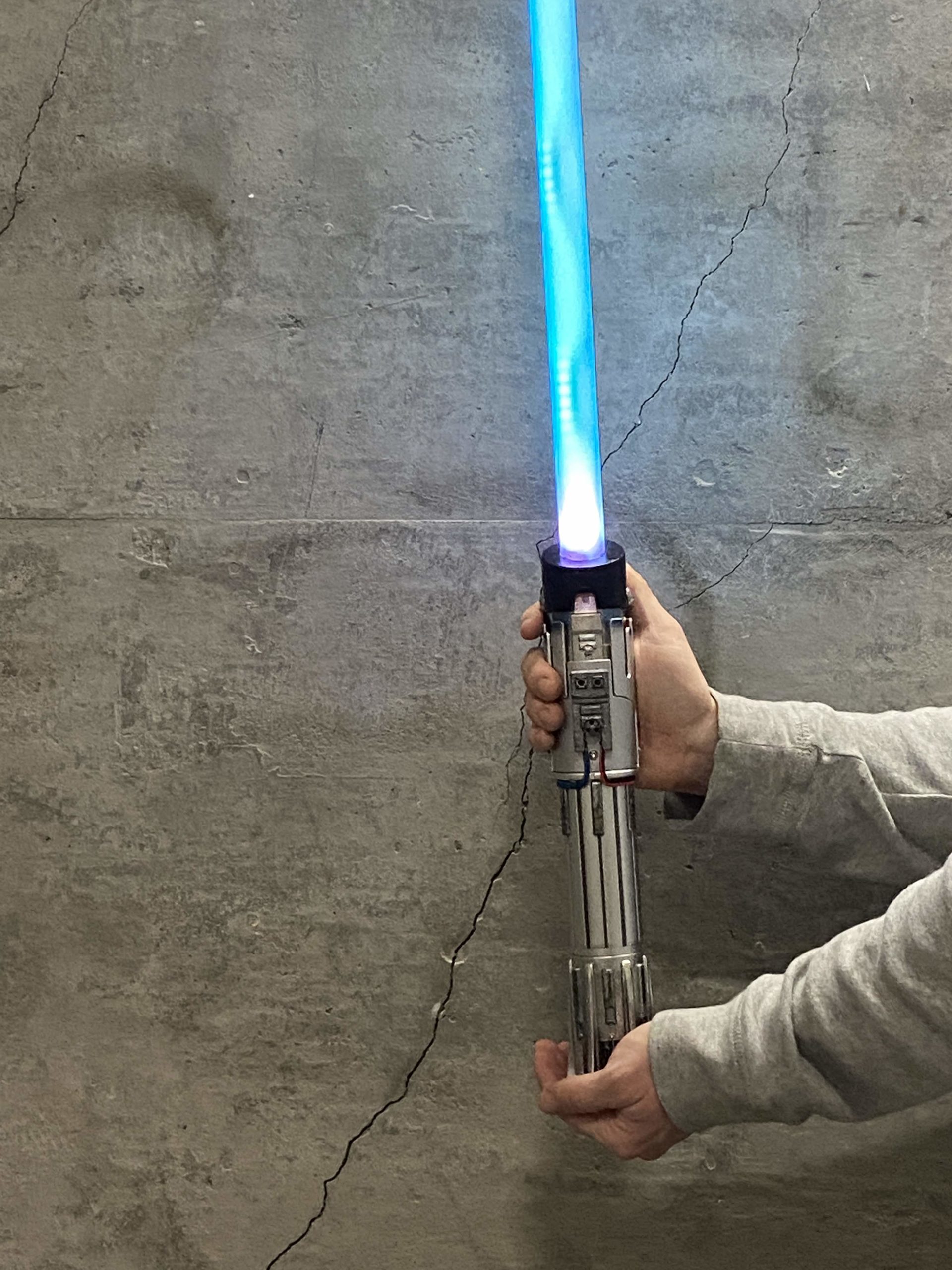
The lightsaber features sounds when the blade is turned on or off along with swing sounds. You can also cycle between five different blade colors. These colors can be changed in the code itself at any time, and other features such as a hum noise can also be added in.
Step 2: Materials and Tools Needed
To complete this project you will need the following materials:
- A Legacy Lightsaber Hilt (Ben Solo one is used here)
- Teensy 3.2
- Prop Shield
- (2x) 3m WS2812B LED Strip (144 LED/meter)
- 1″ Outer Diameter Polycarbonate Tube
- Push Button Switch
- Wires
- 3D Printed Parts: Button Holder and Hilt Adapter
In addition, the following tools and supplies will be needed:
- Soldering iron
- Heat shrink tubing
- 3D printer
- Drill
- Sander / sand paper
- Super glue
- Dremel
You can find a link for all the code related files and 3D printed components here.
Step 3: Electronics Prep
The best thing to do is to connect all the electronics first prior to making any modifications to the hilt. To do so you’ll need to prepare the Teensy and Prop Shield so the code can actually read the audio files off of the Prop Shield (you can find all the custom files needed here):
1. Solder pins and headers onto the Teensy and Prop Shield respectively.
2. Run teensyduinoInstall to add Teensy to Arduino.ide
3. Make sure you have the following libraries included in Arduino.ide (they can be found easily via Google if you need them): Audio, Wire, SPI, SD, SerialFlash, FastLED, NXPMotionSense, EEPROM
4. Connect the Teensy on top of the Prop Shield and load the “EraseEverything” sketch. This clears everything from the Teensy and Prop Shield.
5. Change the USB Type to “Raw HID” and load the “teensytransfertool_AUDIOSPI” sketch.
6. Run command prompt and change directory to the teensytransfer.exe folder (this needs to be unzipped). Put sound files here in .RAW 8.3 format if you want different sound files. The original audio files were found here.
7. Run teensytransfer to transfer audio files to the Prop Shield.
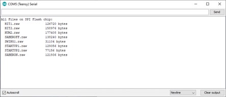
8. Change the USB Type to “Serial” and load the “ListFiles” sketch to make sure files were added.
9. Follow the Motion Sensor section here to calibrate the Prop Shield motion sensors.
10. Load the “lightsaber_code” sketch.
Disclaimer: The code itself might be rough and not the best example of how to perform certain tasks. There are likely more efficient or better ways to write code to do the same thing. No support beyond these instructions is offered with the code.
Step 5: Electronics Wiring
Once the electronics are prepped and the code is loaded then it’s time to test out the electronics before making adjustments to the hilt. The electronics wiring diagram is split up between the hilt and blade:
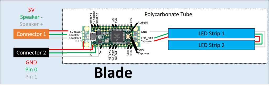
For the Blade wiring, the Connector 2 GND wiring can either go to the pin on the Teensy or Prop Shield. For initial testing you can treat everything as one wiring diagram and omit the connectors (more details on the connectors below). Once you confirm the code is working you can move on to actually modifying the hilt. For a full list of the code behavior and to troubleshoot which components aren’t working properly, reference Step 9 below.
Step 6: Hilt Modifications
The hilt already has electronics in it that are utilized for the custom blade. The hilt appears to have 3 main electronics components: the battery core (contains the batteries and speaker), the main control board, and the blade cavity. As mentioned above, the main control board is not accessible without destroying the hilt itself. For this reason, the connections between the battery core to the main control board needs to be removed, along with the blade connectors for using a legacy blade.
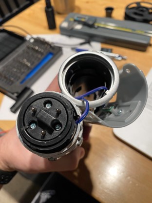
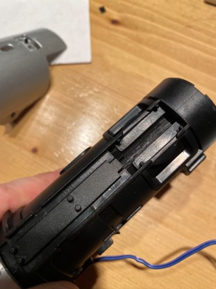
Battery Core Modifications
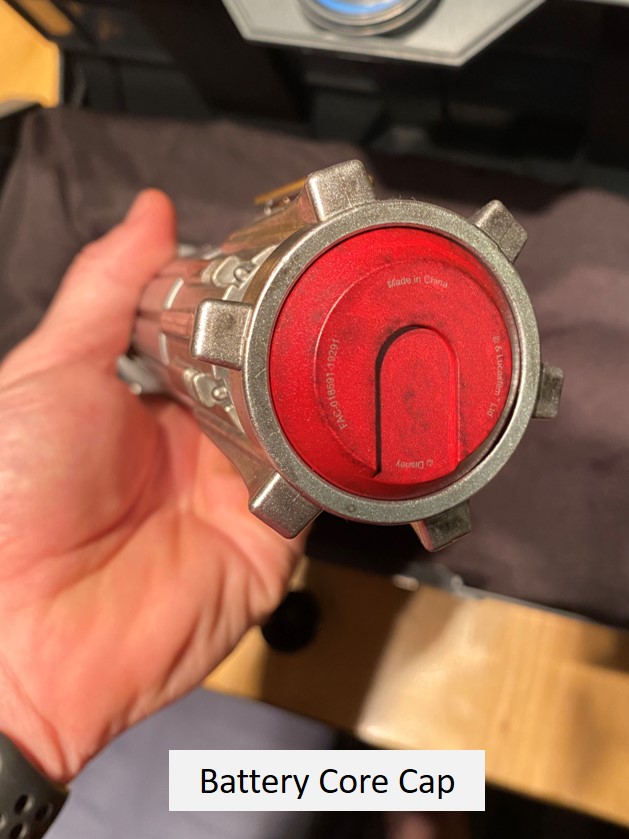
1. Start by unscrewing the bottom cap that holds the battery core in the hilt. Remove the battery core from the hilt.
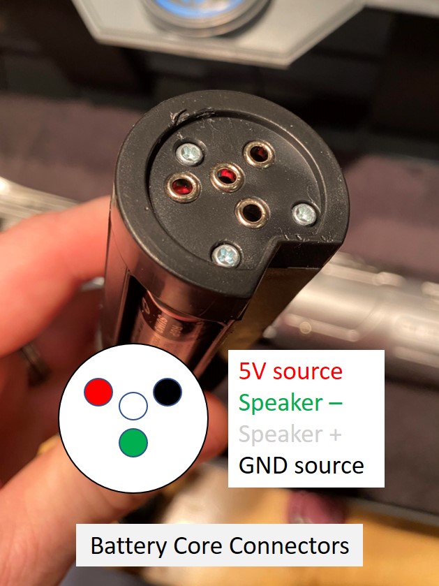
2. The end of the battery core that’s farthest inside the hilt has 4 pins on it that connect this component to the main controller. Remove the screws holding this cap with the pins to expose the wires inside (GND, 5V, Speaker + and Speaker -).
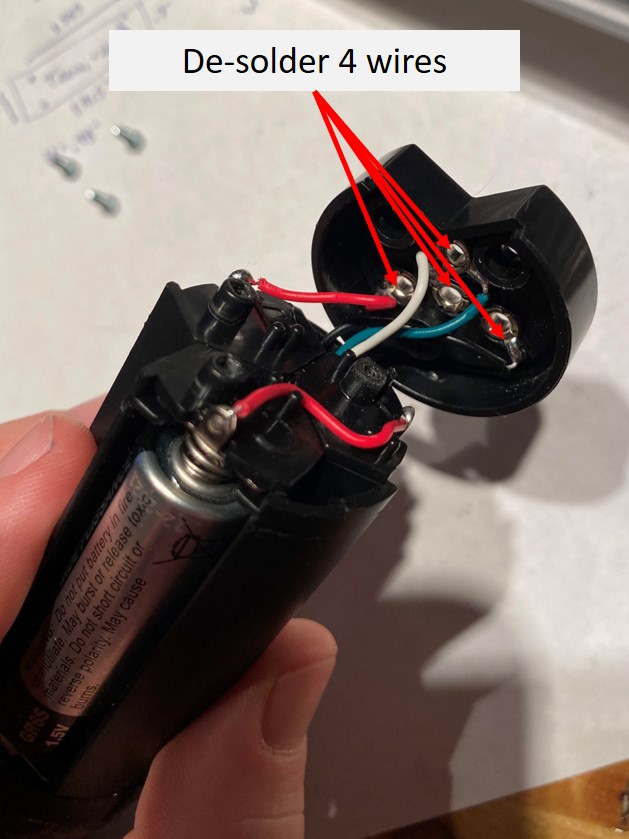
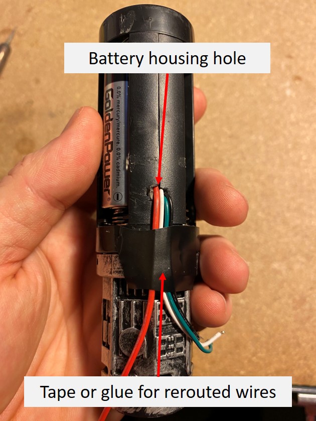
3. De-solder the 4 wires from the pins in the cap. Reroute these wires to the other end of the battery core so they can be routed outside the hilt. A small hole will need to be drilled into the housing for the wires to feed out of.
4. Use a piece of tape or glue to hold the wires down. Make sure the battery core still slides into the hilt.These wires will be extended later and routed outside the hilt to bypass the main controller section.
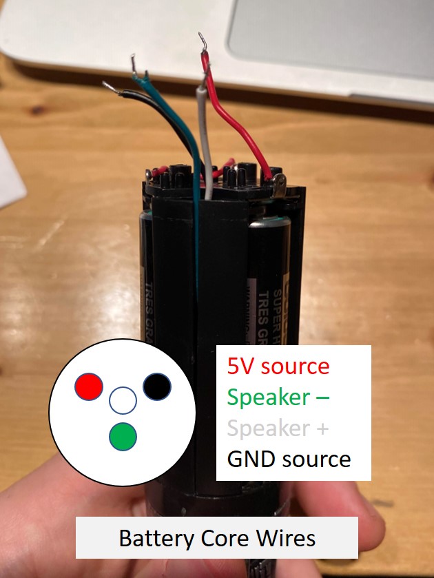
Tip: Color code and/or label your wires so you know which ones are which. This is helpful in keeping the routes clean and making sure everything is connected to the correct pins.
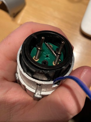
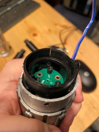
Blade Cavity Modifications
1. Unscrew the 3 screws that connect the blade cavity to the main controller segment.
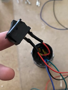
2. Slide the blade cavity components up slowly so the switch panel pops off. Be careful as the switch panel has wires connected to it for turning on and off the blade.

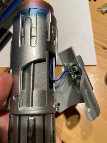
3. Unscrew the switch from the switch plate and switch cover and desolder the wires. Also take all other blade cavity components off the hilt to provide better access to the blade connector pins. The blade aligner (black inner tube) can be set aside and won’t be needed but should be saved if you want to convert the hilt back to use a legacy blade.
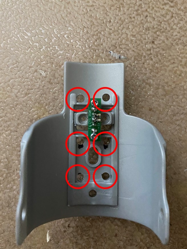
4. Unscrew the screws holding the cap over the blade connector pins. Remove the pins from their holes to provide extra spacing in the blade cavity for the custom blade. Save the pins, springs, screws and cap to reverse the modifications later if desired.
5. Push down and rotate the blade connector pin holder in the hilt so it stays in place in the lowered position. This provides even more space for the custom blade.
6. Drill a few holes in the switch plate to help with wire routing later. These holes can be placed so they’re hidden below the switch cover.
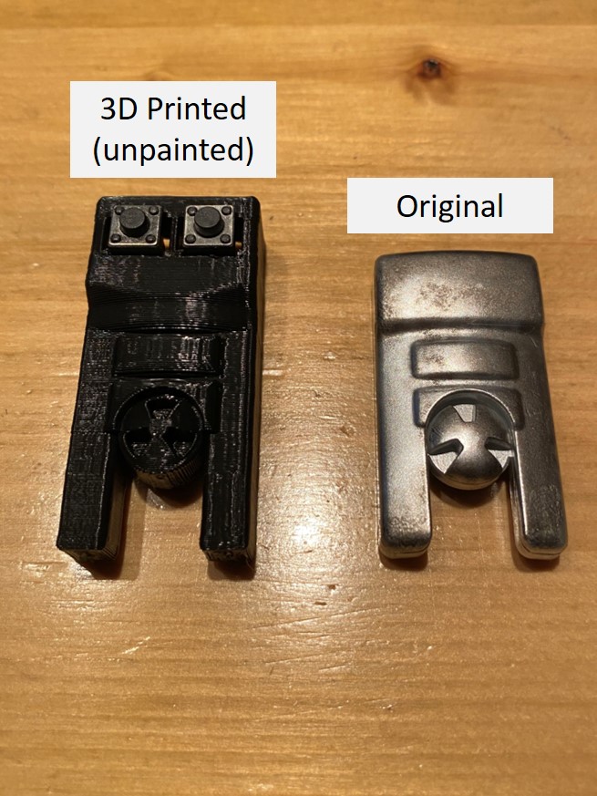
7. The switch cover will be replaced with a 3D printed version that holds two toggle buttons to turn on and off the blade and change the blade color. Assemble the new switch cover onto the switch panel and put the switch back in place. Make sure the switch can still be activated by sliding the new switch cover. Alternatively you can omit this switch and place one in the battery core to free up some space beneath the switch plate. This switch will be turning on and off power to the Teensy so the batteries don’t run out.
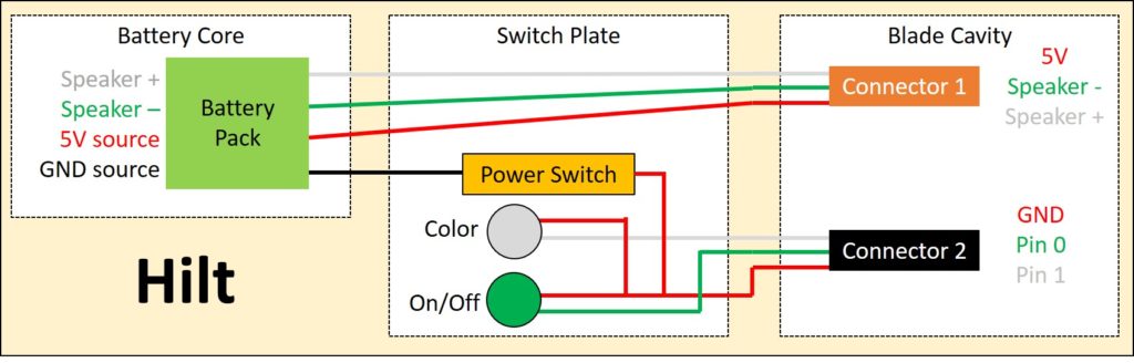
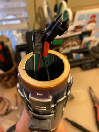
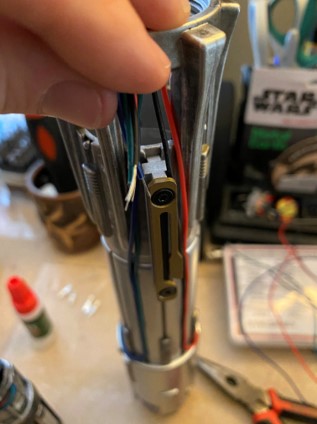
Step 7: Wire Routing
The easiest way to route the wires is from the top of the hilt to the bottom (trust me, this was a trial and error reached conclusion). The blade connection features two connectors. Connector 1 has pins for the 5V power, Speaker – and Speaker + while Connector 2 has pins for GND, Pin 0 (blade on/off) and Pin 1 (blade color change). I put a piece of orange heat shrink tubing on Connector 1 so I knew which one was which.
- The 3 pin connectors used were cut off the LED strips. Attach enough wire to each connector to allow the connectors to stick out of the blade cavity for easy connection of the blade.
- Choose which toggle button you want to control the blade on/off and which one you want to control the blade color change so you know which pins on the connector you want them wired to. Connect together the GND of the two toggle buttons and another wire for power GND.
- If using the switch from the hilt, wire it between the line for 5V.
- Feed 4 wires (5V, GND, Speaker – and Speaker +) from the blade cavity, through the switch panel and below the switch cover. Make sure you have enough length to reach the battery core at the other end of the hilt.
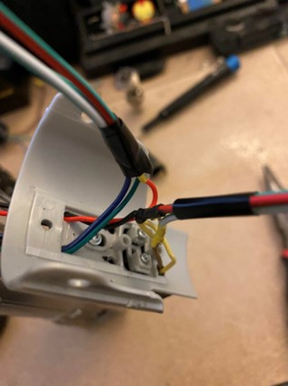
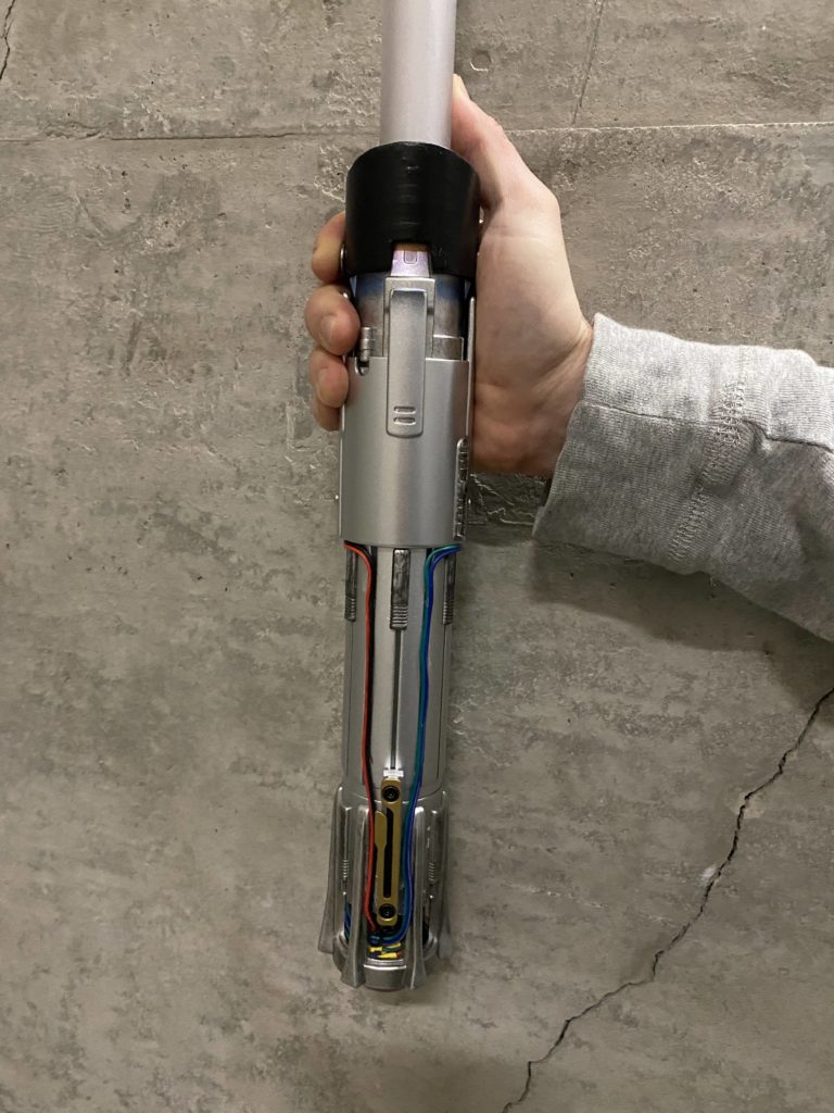
- Route the 4 wires down around the outside of the hilt in a direction of your choosing so they reach the battery core. This part serves as function and aesthetics for the custom blade. Use glue to hold the wires in place, but be aware this may damage the finish on the hilt.
- Connect each of the 4 wires from the top of the hilt to the respective wires from the battery core. Make sure there’s enough slack in the wires to allow the battery core to be removed to change the batteries.
Optional: Put a switch in the battery core (floating above the speaker) to switch on and off power. The downside here is that the cap holding the battery core in the hilt needs to be removed every time you want to turn the power on or off. The upside is there would be more space in the switch panel compartment mentioned previously.
Tip: Color code and/or label your wires so you know which ones are which. This is helpful in keeping the routes clean and making sure everything is connected to the correct pins.
Step 8: Build the Blade
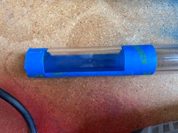
The polycarbonate tube requires some modifications before it can be used.
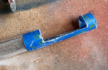
- A cutout needs to be added in to allow the Teensy and Prop Shield to fit. Tape off the tube to show the window that needs to be cut out. The window should be about 0.5″ from the edge and 2.5″ long. Start by cutting half of the diameter away and test to see how the electronics fit in. The tube and electronics should both fit into the blade cavity of the hilt so cut away more material as needed.
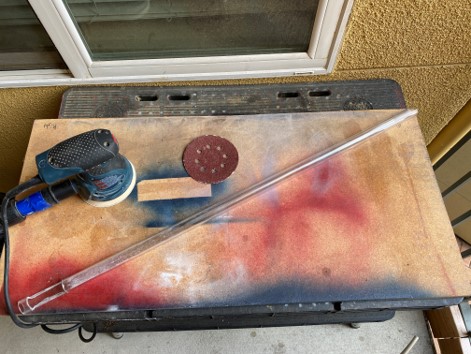
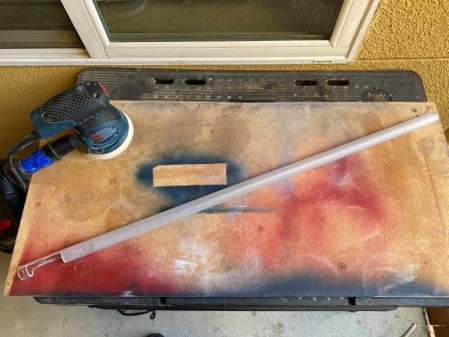
- The blade also needs to be frosted to hide the actual LED strips inside it and make the blade seem like it’s one long tube of light. Use sand paper to make the tube foggy. It’s best to start with a higher grit sandpaper (180 grit was used here) as only a small layer of material needs to be distorted.
- Stick the two LED strips together and cut them and the tube to length. The final blade length is based on your preference. Solder the ends of the LED strips together so they are in series. Solder the other end to the Prop Shield.
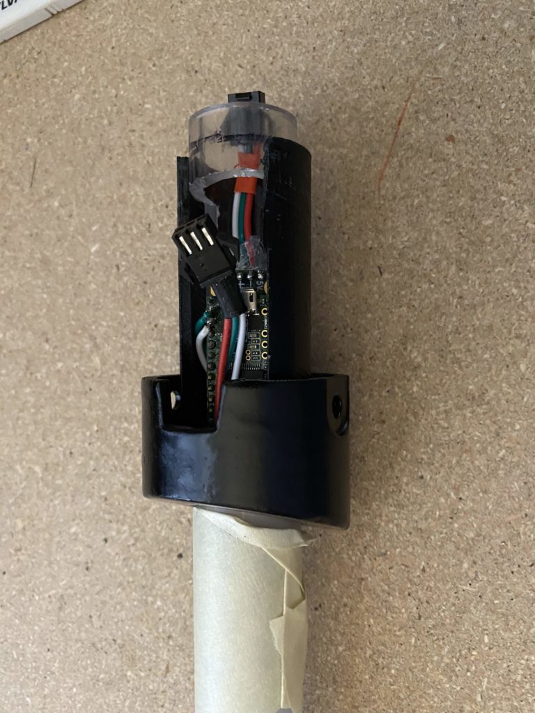
- Wrap the LED strips in parchment paper and feed them into the tube. Place the Teensy and Prop Shield into the blade window and feed the connectors out the end of the blade. Use glue to fix the electronics in place. The image below shows Connector 2 wrapped under the Teensy to make connections easier.

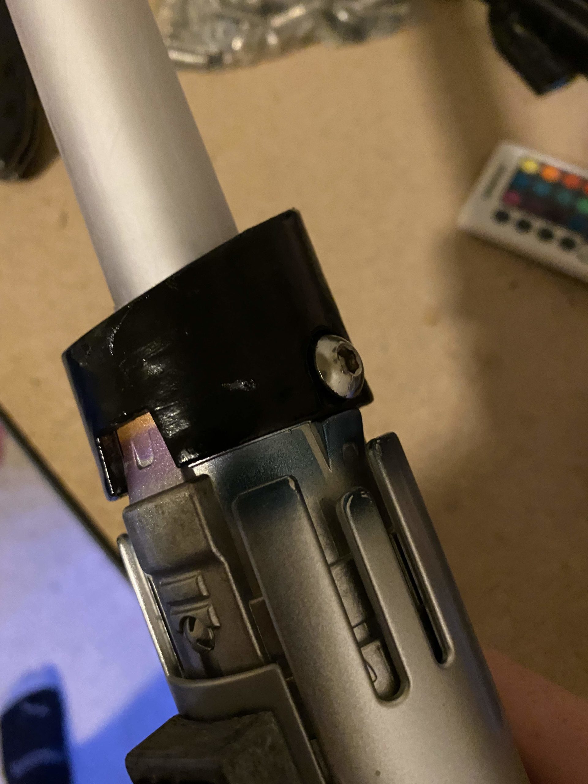
- Attach the Hilt Adapter pieces over the electronics window of the blade and secure in place with glue. You can put a cap on the end of the tube if desired as well. The hilt adapter was designed to provide a secure connection between the blade and hilt. To disguise the connection and provide more stability the adapter has a geometric feature on it similar to Darth Vader’s hilt. I also used two screws on either side of the feature to secure the parts together. Unfortunately this did require drilling more holes in the hilt so this is optional and avoid this if you don’t want to modify the hilt further.
Step 9: Testing the Blade
At this point your blade should be done and can be tested. When connecting the blades, make sure you connect the correct pins together to avoid damaging the electronics. A good method is to make sure the blade power is completely off first, then connect whichever connector has the GND pin first (Connector 2 based on the wiring scheme from above).
The once connected the blade can be operated as follows:
- Turn on the blade power using the switch you wired up (either in the switch cover or in the battery core). A startup noise should play letting you know the electronics have power. The first LED should also light up to the current blade color.
- Turn the blade on by using one of the toggle buttons. The blade will animate turning on and play a sound.
- Swing the blade and a swing sound should play.
- Push the other toggle button to cycle the blade color.
- Turn the blade off by using the toggle button. Make sure to switch off blade power when done to avoid draining the batteries.
Step 10: Have Fun!
Hopefully by this point your blade is complete! Feel free to customize your hilt further to your liking as well. On the code side, there are areas where you can change the colors the blade cycles through and also load different audio files if desired. If you completed this project we’d love to see it so send us your finished light saber or tag us on social media!


